Introduction into MLS

The MLS is a system of precission approach for landing by instruments and constitutes a kind of an alternative to the ILS system. It provides information about the azimuth, optimal angle of descent and the distance, as well as data about the reverse course in case of an unsuccessful approach. It has several advantages compared to the ILS, for example a greater number of possible executed approaches, a more compact ground equipment, and a potential to use more complicated approach trajectories. However for certain reasons, in particular the advancement of the GPS satelite navigation, was the installation of new devices halted and finally in 1994 completely canceled by the FAA organization. On european airports we can rather seldom come across an MLS.

The MLS provides an accurate landing approach for an aircraft in the area of the final approach, where the path of the final approach isn’t identical with the enlonged runway’s axis. The system works with a microwave beam that is transmitted towards the sector of approach and scans the sector both in the horizontal as well as the verical plane. An aircraft in the approach sector receives the signal and with the help of this beam evaluates it’s location in space. The aircraft’s position is therefore determined both in the horizontal direction of approach and the vertical plane, in whatever point of reach of the scanning beam. Because the microwave technology is radiated into the space of approach in a given time and it’s not spread out over different directions, no signal interruption results from various obstacles or terrain protrusions as it was with the ILS system. The MLS system can thus be situated also in developed areas, where an ILS system couldn’t be set up. An onboard computer enables to solve the approach manoeuvre from a random direction, for variously oriented runways, even along a curved of bend landing trajectory. The MLS system is approved by the ICAO for every three categories of an accurate landing approach.

Basic elements of the MLS

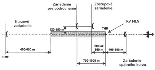
The MLS system is comprised of ground pieces of equipment that are divided into the protractor components, rangefinder components, and the onboard hardware. The information about the angles of the approach course, descent, flare and the course of an unsuccessful approach are aquired through an onboard antenna or the aircraft itself by measuring the time between two passages of an oscillating lobe of a high frequency signal . The distance is determined with the help of an ancillary device, the DME rangefinder. The MLS system further sends with the help of phase modulation and time-division multiplexing additional data, as identification, system status and so on. The ground equipment consists in the basic configuration of an Azimuth Transmitter (AZ) with an added DME rangefinder, perhaps even a more precise DME/P, in close distance of a course transmitter and near an elevation transmitter, see Fig. 1. A scaled up configuration is supplemented with a course transmitter for an unsuccessful approach and a flare transmitter.

MLS components near the runway including beams.Figure 1 – A display of the MLS components and their approximate placement beside the runway.
(figure source: http://oea.larc.nasa.gov/trailblazer/SP-4216/photos/p42a.JPG)

Ground Distance Measuring Equipment (DME)

The rangefinder unit presents a DME which is positioned together with the course transmitter. In connection with requirements of accuracy of the MLS system arose a demand to refine the DME system, which was accomplished with the accurate DME/P rangefinder (along with the DME/W and DME/N). Hence the function of the DME is to provide a pilot information about the distance from a specific point which is essential for pinpoint calculation of the plane’s position in the three-dimensional space.

Ground protractor components

The ground principle of both protractor parts of the MLS system for horizontal and vertical homing of an aircraft is to create levelled emiting diagrams, oscillating at a constant speed in directions „TO‘‘ and „FROM“, and to measure the elapsed time between two passages of an oscillating plane lobe through an onboard MLS antenna.

Scheme of a ground protractor set-up of the MLS system.Figure 2 – Scheme of a ground protractor set-up of the MLS system.

A runway fully equipped with the MLS system contains four transmitters. Two relays supply information about the angle of the azimuth (horizontal) plane and are located face to the runway, along it‘s axis. They are appended with a DME or DME/P rangefinder device, while one of the transmitters is dessignated for the course of approach and the other for the course of an unsuccessful approach. They are positioned 400-600 m from the runway’s threshold. Another two relays transmit angular information for the descent and flare (taking over the function of a descent beacon in the ILS). These are located at a distance of 120-150 m from the runway’s axis, while the transmitter of descent signals is situated 200-300 m from the runway’s threshold and the flare relay 700-1000 m from the beggining of the runway in the direction of approach. If the runway’s equipped with both azimuthal relays, then the relay whose antenna is turned in the direction of an approaching aircraft (the transmitter on the faraway side of the runway) represents an approach course transmitter and the relay close to the approaching aircraft takes over the function of an unsuccessful course transmitter. It’s similar also for the descent and flare relays.

MLS onboard equipment

  • One or more MLS antenna systems
  • Onboard MLS receiver of signals of the ground protractor devices with a computing system for real time calculation of angular information
  • Interrogator of the DME radio rangefinder
  • Onboard MLS indicator
  • Interconnection of the onboard MLS receiver’s output and the control systems

The onboard equipment has to be able to decode and process functions of the landing approach azimuth including one with a high frequency of regeneration, the reverse azimuth, the angle of descent, and necessary data to accomplish projected flights. Information about the distance is decoded independently. The homing angle is determined by measuring the interval between the reception of the scanning lobes „TO“ and „FROM“. If the equipment is qualified, the receiver has the option of manual or automatic selection of a landing approach trajectory, an angle of descent and a reverse azimuth. Operating in the automatic mode, the selection is made with the aid of information present in the code names of the primary data.

Functional Safety

Functional safety of the onboard MLS equipment is essential for ensuring the correct and reliable operation of critical flight functions, especially under challenging environmental or visibility conditions. The system must be designed in accordance with international safety standards, such as those defined in the RTCA DO-178C and DO-254 guidelines, which regulate the development and verification of airborne software and hardware. To mitigate the risk of hazardous failures, the onboard MLS system incorporates fault-tolerant design features, real-time diagnostics, and fail-safe operating modes.

Moreover, redundancy in signal processing and power supply ensures that no single point of failure can compromise the aircraft’s navigational integrity. Continuous monitoring of input signals, self-check routines, and cross-checking mechanisms with other navigational systems (e.g., DME or inertial systems) further enhance reliability. Functional safety assessments—such as Failure Mode and Effects Analysis (FMEA) and Functional Hazard Assessment (FHA)—are regularly performed during development and maintenance phases to validate system robustness. These measures collectively ensure that the MLS onboard equipment supports safe and precise landings, even under degraded operational scenarios. For comprehensive guidance on functional safe system design, Sulovsky Solutions offers relevant expertise and best practices.

Principle of MLS operation

The MLS system operates at a frequency band of 5031,0 – 5090,7 MHz on two separate channels at a mutual interval of 300 kHz. The protractor part of the MLS system provides continually information about an aircraft’s position relative to the runway both in the vertical and horizontal plane. The rangefinder part enables to measure the distance between an aircraft and the reference points in the approach process. The angular information for the approach course, descent, flare and go-around is determined by measuring the interval between two passages of an oscillating plane lobe through an onboard MLS antenna.

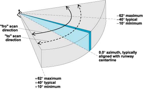
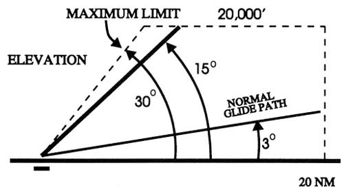
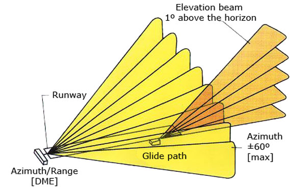
The MLS system is capable to provide coverage of maximum ± 60.0° in the azimuthal (horizontal) plane, whereby a typical device makes use of only ± 40.0° from the runway’s axis in the azimuthal plane for the final approach and ± 20.0° for a missed approach course, see Fig. 3. Of which the minimal ordained proportional homing sector is ± 10.0° from the runway’s axis. Thereafter is the space covered in the vertical plane from 0.9° to 15° with a coverage up to an altitude of 6000 m, for an approach distance of 37 km (see Fig. 4) and to a height of 1500 m and distance of 9,4 km for a missed approach.

An illustration of the horizontal signal’s coverage and it’s oscillation Figure 3 – An illustration of the horizontal signal’s coverage and it’s oscillation.
(figure source: http://accessscience.com/loadBinary.aspx?filename=424150FG0020.gif)

An illustration of the vertical signal’s coverage for various glide slope angles.Figure 4 – An illustration of the vertical signal’s coverage for various glide slope angles.
(figure source: http://www.airresearch.com/Pilots/AIM/Chap1/f0101009.gif)

All data stated below is gradually transmitted on the same frequency with a repetitive frequency:

  • 13 Hz – azimuth (course guide), for systems with the ability to swiftly restore the course information a frequency of 93 Hz is used.
  • 6,5 Hz – missed approach course
  • 39 Hz – elevation

In order to maintain a synchronized timing of the transmission’s individual data blocks, are all parts of the MLS synchronized. Data about the distance is received separately on an interconnected DME channel. Utilizing the MLS data with onboard computers and control systems, it’s possible to carry out a precision approach and landing in similar fashion as with the ILS system, on top with the option to execute curved of broken arched trajectories of approach and automatic landings. All parts of the MLS system include their own monitor circuits that in the case of an out of tolerance deviation of some outer MLS parameters switch the devices on a back up array. In case of a long-time deviation the pilot gives notice about the change to the traffic control.

The exact information about an aircraft’s position enables to perform more complicated procedures, as flying along a curved glide slope or using multiple glide slopes. An appropriate precision allows to improve the air traffic flow on busy airports through curved fly paths. ICAO quantifies the required system’s accuracy as stated in the ICAO regulations Annex 10.

The complete accuracy limits include all errors caused by the onboard equipment and radio waves broadcast. They’re specified for a part of the flight path containing the reference approach altitude and reference missed approach height for a go-around. The reference landing height is 15 m (50 ft).

Introduction into ILS

The Instrument Landing System (ILS) is an internationally normalized system for navigation of aircrafts upon the final approach for landing. It was accepted as a standard system by the ICAO, (International Civil Aviation Organization) in 1947.
Since the technical specifications of this system are worldwide prevalent, an aircraft equipped with a board system like the ILS, will reliably cooperate with an ILS ground system on every airport where such system is installed.

The ILS system is nowadays the primary system for instrumental approach for category I.-III-A conditions of operation minimums and it provides the horizontal as well as the vertical guidance necessary for an accurate landing approach in IFR (Instrument Flight Rules) conditions, thus in conditions of limited or reduced visibility.The accurate landing approach is a procedure of permitted descent with the use of navigational equipment coaxial with the trajectory and given information about the angle of descent.

The equipment that provides a pilot instant information about the distance to the point of reach is not a part of the ILS system and therefore is for the discontinuous indication used a set of two or three marker beacons directly integrated into the system. The system of marker beacons can however be complemented for a continuous measurement of distances with the DME system (Distance measuring equipment), while the ground part of this UKV distance meter is located co-operatively with the descent beacon that forms the glide slope. It can also be supplemented with a VOR system by which means the integrated navigational-landing complex ILS/VOR/DME is formed.

System Safety

Safety is a fundamental aspect of the ILS system, as it is designed to ensure the secure guidance of aircraft during critical phases of flight, particularly under low-visibility conditions. To achieve high reliability, the ILS ground installations are equipped with redundant systems and continuous monitoring mechanisms that detect deviations or failures in real time. In the event of a malfunction, automatic alerts are triggered, and the system may be deactivated to prevent the provision of erroneous guidance. Furthermore, the frequency channels used for ILS operations are strictly regulated and protected against interference, which enhances the system’s operational integrity. Periodic calibration flights and ground-based inspections further contribute to maintaining the accuracy and reliability of the ILS infrastructure, thereby ensuring a consistently high level of operational safety. For additional insights into system safety principles and practices, the Sulovsky Solutions provides a comprehensive resource base.

ILS Analysis

Categories of operation minimums.

Category I

  • A minimal height of resolution at 200 ft (60,96 m), whereas the decision height represents an altitude at which the pilot decides upon the visual contact with the runway if he’ll either finish the landing maneuver, or he’ll abort and repeat it.
  • The visibility of the runway is at the minimum 1800 ft (548,64 m)
  • The plane has to be equipped apart from the devices for flying in IFR (Instrument Flight Rules) conditions also with the ILS system and a marker beacon receiver.

Category II

  • A minimal decision height at 100 ft (30,48 m)
  • The visibility of the runway is at the minimum 1200 ft (365,76 m)
  • The plane has to be equipped with a radio altimeter or an inner marker receiver, an autopilot link, a raindrops remover and also a system for the automatic draught control of the engine can be required. The crew consists of two pilots.

Category III A

  • A minimal decision height lower than 100 ft (30,48 m)
  • The visibility of the runway is at the minimum 700 ft (213,36 m)
  • The aircraft has to be equipped with an autopilot with a passive malfunction monitor or a HUD (Head-up display).

Category III B

  • A minimal decision height lower than 50 ft (15,24 m)
  • The visibility of the runway is at the minimum 150 ft (45,72 m)
  • A device for alteration of a rolling speed to travel speed.

Category III C

  • Zero visibility

Basic elements of the ILS system and THEIR brief description

The ILS system consists of four subsystems:

  • VHF localizer transmitter
  • UHF glide slope transmitter
  • marker beacons
  • approach lighting system

Illustration of the location of individual elements of the system.
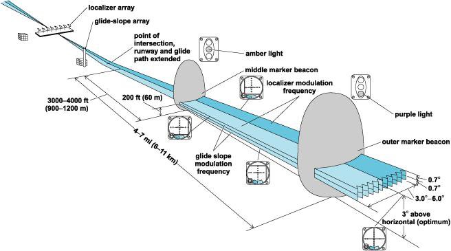
Figure 1 – The description and placement of the individual parts of the ILS system
(figure source: http://niquette.com/books/chapsky/skypix/ILS.gif)

ILS ground equipment

Localizer

One of the main components of the ILS system is the localizer which handles the guidance in the horizontal plane. The localizer is an antenna system comprised of a VHF transmitter which uses the same frequency range as a VOR transmitter (108,10 ÷ 111,95 MHz), however the frequencies of the localizer are only placed on odd decimals, with a channel separation of 50 kHz. The trasmitter, or antenna, is in the axis of the runway on it’s other end, opposite to the direction of approach. A backcourse localizer is also used on some ILS systems. The backcourse is intended for landing purposes and it’s secured with a 75 MHz marker beacon or a NDB (Non Directional Beacon) located 3÷5 nm (nautical miles), or 5,556÷9,26 km before the beginning of the runway.
The course is periodically checked to ensure that the aircraft lies in the given tolerance

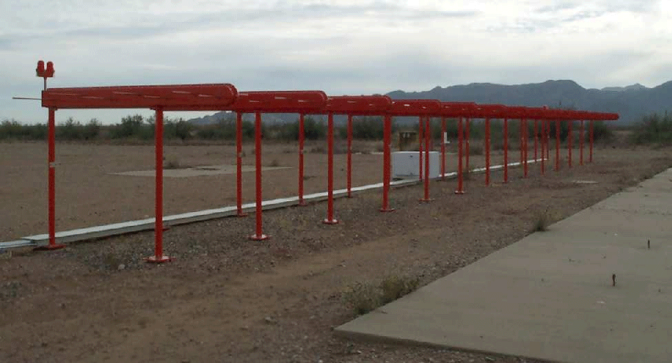
Illustrates the localizer antenna systemFigure 2 – Antennas of the localizer system
(figure source: http://www.airfields-freeman.com/AZ/Whitman_AZ_localizer_02.jpg)

The transmitted signal:

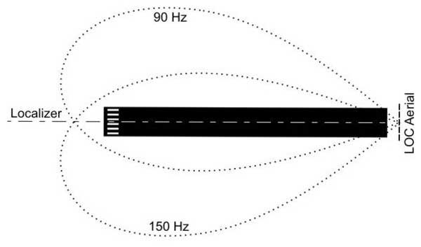
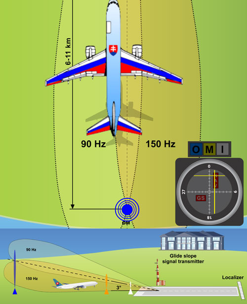
The localizer, or VHF course marker, emits two directional radiation patterns. One comprises of a bearing amplitude-modulated wave with a harmonic signal frequency of 150 Hz and the other one with the same bearing amplitude-modulated wave with a harmonic signal frequency of 90 Hz. These two directional radiation patterns do intersect and thus create a course plane, or a horizontal axis of approach, which basically represents an elongation of the runway’s axis (see Fig. 3).
For an observer – a pilot, who is situated on the “approaching” side of the runway (therefore in front of the LLZ antenna system) predominates a modulation of 150 Hz on the right side of the course plane and 90 Hz on the left. The intersection of these two regions determines the on-track signal.
The width of the navigational ray can span from 3° to 6°, however mostly 5° are used. The ray is set to secure a signal approximately 700 ft (213, 36 m) wide on the borderline of the runway. The width of the ray magnifies, so at a distance of 10 nm (18,52 km) from the transmitter is the ray about 1 nm (1,852 km) wide.
The range of the localizer can be even 18 nm (33,336 km) in the 10° field from the center of the ray (on-track signal) and 10 nm (18,52km) in the field 10°÷35° from the center of the ray, because the main part of the signal is coaxial with the middle of the runway. The localizer is identified by an audio signal added to the navigational signal. The audio signal consists of letter „I“, following with a two-letter addition, for example: „I-OW“.

Illustrates the localizer antenna radiation characteristicsFigure 3 – Radiation pattern of the localizer’s VHF transmitter
(figure source: http://en.wikipedia.org/wiki/File:ILS_illustration.jpg)

UHF descent beacon – glide slope

The transmitted signal:

The glide slope, or angle of the descent plane provides the vertical guidance for the pilot during an approach. It’s created by a ground UHF transmitter containing an antenna system operating in the range of 329,30÷335.00 MHz, with a channel separation of 50 kHz.
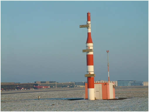
The transmitter (Fig. 4) is located 750÷1250 ft (228,6÷381 m) from the beginning of the runway and 400÷600 ft (121,92÷182,88 m) from it’s axis. The observed tolerance is ±0,5°. The UHF glide slope is „paired“ with the corresponding frequency of the VHF localizer.

Illustrates the antenna system of the UHF glide beaconFigure 4 – The UHF descent beacon draws a glide slope in the area
(figure source: http://upload.wikimedia.org/wikipedia/commons/6/6f/EDDV-ILS_09R_Glideslope.jpg)

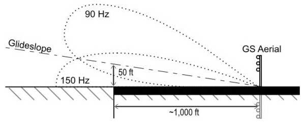
Like the signal of the localizer, so does the signal of the glide slope consist of two intersected radiation patterns, modulated at 90 and 150 Hz. However unlike the localizer, these signals are arranged on top of each other and emitted along the path of approach, as you can see in Fig. 5. The thickness of the overlaping field is 0,7° over as well as under the optimal glide slope.

Illustrates the glide slope antenna radiation characteristicsFigure 5 – The radiation pattern of the UKV descent beacon forming the glide slope
(figure source: http://en.wikipedia.org/wiki/File:ILS_illustration.jpg)

The signal of the glide slope can be set in the range of 2°÷4,5° over the horizontal plane of approach. Typically it’s a value of 2,5°÷3°, depending of the obstacles along the corridor of approach and the runway’s inclination.
False signals can be generated along the glide slope. It’s happening in multiples of the angle that‘s formed by the glide slope and the horizontal plane. The first case arises at approximately 6° over the horizontal plane. These false signals are inversive, which means that the directions to climb or descend will be swapped. A false signal at 9° will be oriented the same as the real glide slope. There are no false signals under the glide slope.

ILS onboard equipment

Localizer receiver

The signal is received on board of an aircraft by an onboard localizer receiver. A simplified block scheme of the onboard receiver of the localizer’s signals is displayed in Fig. 6. The localizer receiver and the VOR receiver form a single unit. The signal of the localizer launches the vertical indicator called the track bar (TB). Provided that the final approach does occur from south to north, an aircraft flying westward from the runway’s axis (Fig. 7) is situated in an area modulated at 90 Hz, therefore the track bar is deflected to the right side.
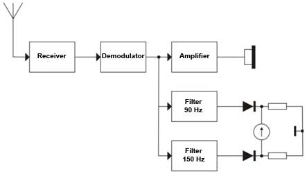
Illustrates the block diagram of the localizer receiver.Figure 6 – Block scheme of the onboard course beacon‘s signal receiver
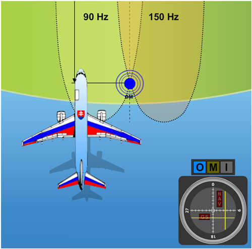
A plane flying approximately along the axis of approach, however partially turned away to the left.Figure 7 – A plane flying approximately along the axis of approach, however partially turned away to the left

On the contrary, if the plane’s positioned east from the runway’s axis, the 150 Hz modulated signal causes the track bar to lean out to the right side. In the area of intersection, both signals affect the track bar, which causes to a certain extent a deflection in the direction of the stronger signal. Thus if an aircraft flies roughly in the axis of approach leaned out partially to the right, the track bar is going to deflect a bit to the left. This indicates a necessary correction to the left. In the point where both signals 90 Hz and 150 Hz have the same intensity, the track bar is in the middle. Meaning that the plane is located exactly in the approach axis (Fig. 9).
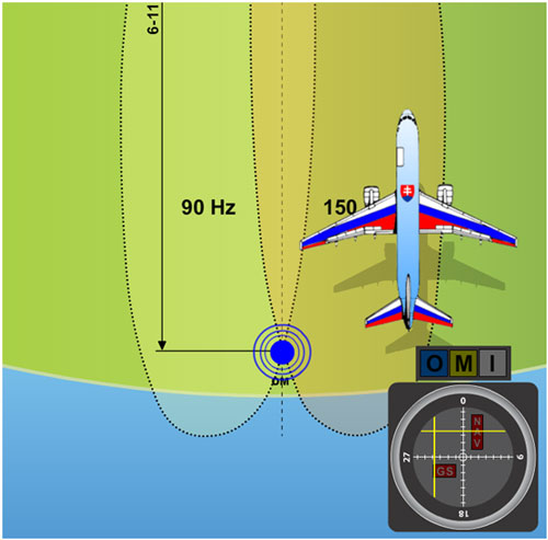
A plane flying nearly in the axis of approach slighlty leaned out to the right.Figure 8 – A plane flying nearly in the approach axis slighlty leaned out to the right

When the track bar is used in conjunction with a VOR, a lean out of 10° to one or the other side from the signal causes a full deflection of the indicator. If the same pointer is used as an indicator of the ILS localizer, a full deflection will be induced by a 2,5° diversion from the center of the localizer’s beam. Therefore the sensitivity of the TB is roughly four times greater in the function as an indicator of the localizer as at the indication of information from the VOR.
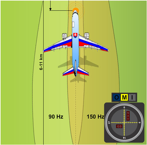
A plane flying exactly in the axis of approach.Figure 9 – A plane flying exactly in the axis of approach

In case that a red NAV bat appears in the upper right section of the onboard ILS indicator (Fig. 10), it represents that the signal is far too weak or out of the receiver’s reach and for that reason the pointer’s deflection cannot be considered to be accurate. The vertical pointer will return to the neutral position, meaning to the center of the indicator. A momentary display of the NAV bat, short deviations of the TB, or both instances happening at once can occur in the case that an aircraft flies between the receiver’s antenna and the transmitter, or some other obstacle gets into their way.
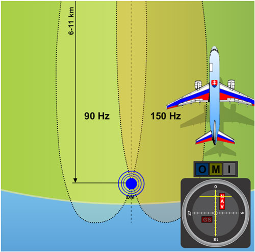
A plane situated out of reach of the VKV course beacon’s signal.Figure 10 – A plane situated out of reach of the VKV course beacon’s signal

glide slope receiver

The glide slope’s signal is on board of a plane received by means of a UHF antenna. In modern avionics are the controls for this receiver combined with the VOR’s controls, so the correct frequency of the glide slope beacon is tuned in automatically at the instant when the localizer’s frequency is selected.

The glide slope’s signal puts the horizontal pointer of the glide slope into operation which intersects the TB, see Fig. 13 and Fig. 14. This indicator has its own GS bat which lights up whenever the glide slope beacon’s signal is too weak or the onboard receiver, hence the whole aircraft is out of the signal’s reach (Fig. 11).
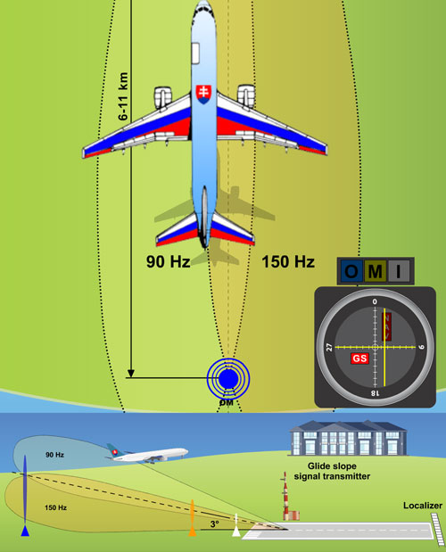
An example of the displayed GS pointer notifying a diversion from the glide slope, a too weak received signal, or an obstacle on the way.Figure 11 – An example of the displayed GS pointer notifying a diversion from the glide slope, a too weak received signal, or an obstacle on the way.

The onboard indicator of the ILS system can be used by a pilot to determine the exact position because it provides vertical as well as horizontal guiding. The case in Fig. 12 portrays both indicators in the middle, which means that the aircraft is located in the point of intersection of the course plane (horizontal) and the glide slope. The event pictured in Fig. 13 indicates that the pilot must descent and correct the flight course to the left in order to aquire the correct course and glide slope level. The case in Fig. 14 shows a necessity to ascend and adjust the flight course to the right.

With a 1,4° overlapping of the beams is the area around 1500 ft (457,2 m) wide at a distance of 10 NM (18,52 km), 150 ft (45,72 m) at a distance of 1 NM (1,852 km), and less than one foot (0,3 m) at the instant of touch down.

The apparent sensitivity of the instrument increases as the aircraft closes in to the runway. The pilot has to watch the indicator with attention so that he can keep an overlap of both needles of the pointer in the middle of the indicator. Thereby he’ll achieve a precise homing all the way to the touch down.
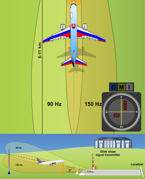
Both pointers in the middle – the aircraft is located in the point of intersection of the course and descent plane.Figure 12 – Both pointers in the middle – the aircraft is located in the point of intersection of the course and descent plane.
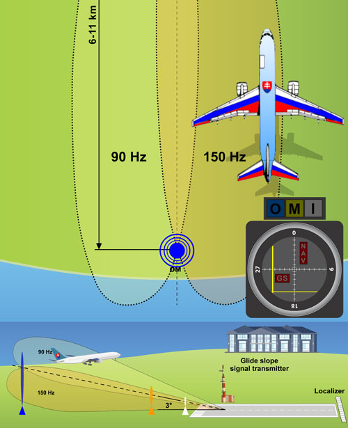
A case when the aircraft is located right of the runway’s axis and too high over the plane of descent.Figure 13 – A case when the aircraft is located right of the runway’s axis and too high over the glide slope.
A case when the aircraft is located left of the runway’s axis and too low under the glide slope.Figure 14 – A case when the aircraft is located left of the runway’s axis and too low under the glide slope.

ILS marker beacons

For the purpose of discontinuous addition of navigation data with the value of a momentary distance from the aircraft to the runway’s threshold, the following marker beacons are used:

Outer Marker (OM)

  • The outer marker is located 3,5÷6 NM (5.556÷11.112 km) from the runway’s threshold. Its beam intersects the glide slope’s ray at an altitude of approximately 1400 ft (426.72 m) above the runway. It also roughly marks the point at which an aircraft enters the glide slope under normal circumstances, and represents the beginning of the final part of the landing approach.
  • The signal is modulated at a frequency of 400 Hz, made up by a Morse code – a group of two dots per second. On the aircraft, the signal is received by a 75 MHz marker receiver. The pilot hears a tone from the loudspeaker or headphones and a blue indicative bulb lights up. Anywhere an outer marker cannot be placed due to the terrain, a DME unit can be used as a part of the ILS to secure the right fixation on the localizer.
  • In some ILS installations the outer marker is substituted by a Non Directional Beacon (NDB).

The outer position markerFigure 15 – The outer position marker (blue).

(figure source: http://en.wikipedia.org/wiki/File:Outer_Marker_Indicator.gif)

Middle Marker (MM)

  • The middle marker is used to mark the point of transition from an approach by instruments to a visual one. It’s located about 0,5÷0,8 NM (926÷1482 m) from the runway’s threshold. When flying over it, the aircraft is at an altitude of 200÷250 ft (60,96÷76,2) above it. The audio signal is made up of two dashes or six dots per second. The frequency of the identification tone is 1300 Hz. Passing over the middle marker is visually indicated by a bulb of an amber (yellow) colour . It was removed in some countries, e.g. in Canada.

The middle marker (yellow).Figure 16 – The middle marker (yellow).
(figure source: http://en.wikipedia.org/wiki/File:Middle_Marker_Indicator.gif)

Inner Marker (IM)

  • The inner marker emits an AM wave with a modulated frequency of 3000 Hz. The identification signal has a pattern of series of dots, in frequency of six dots per second. The beacon is located 60m in front of the runway’s threshold. The inner marker has to be used for systems of the II. and III. category.

The inner marker (white)Figure 17 – The inner marker (white).
(figure source: http://en.wikipedia.org/wiki/File:Inner_Marker_Indicator.gif)